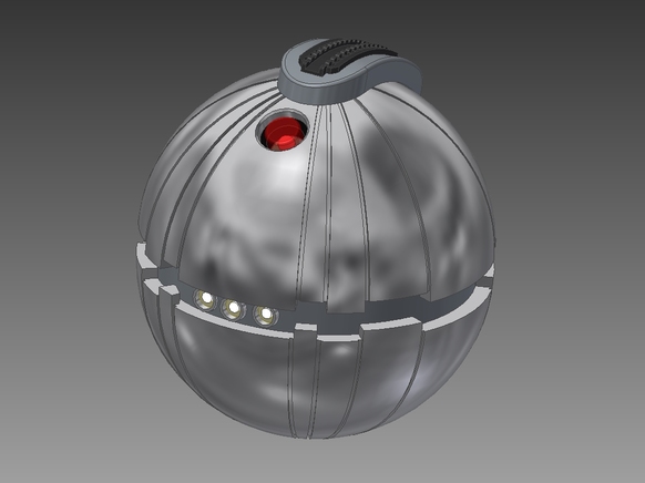
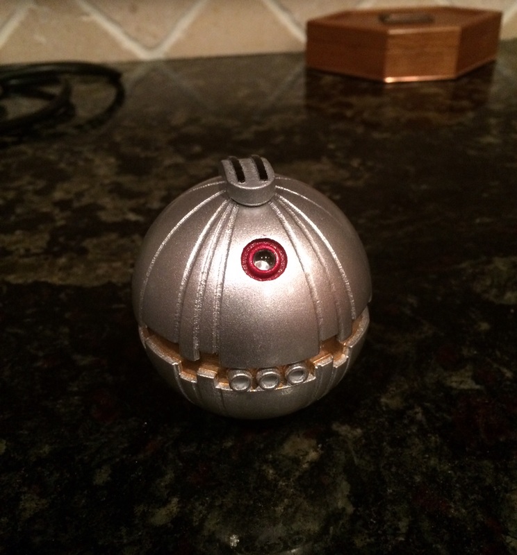
Thermal Detonator - Star Wars 16 June 2015
Completely constructed in steel - With some interpretation eBay SUCKS!!!
An Immortal Contemplating The Ephemeral.
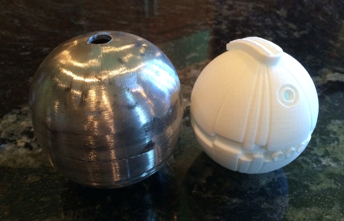
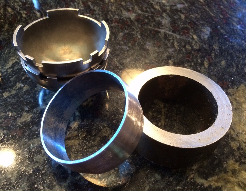
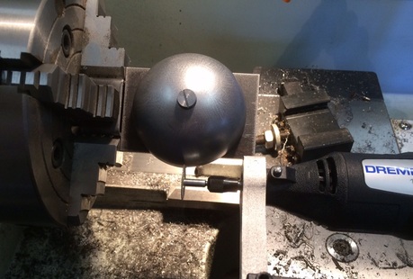
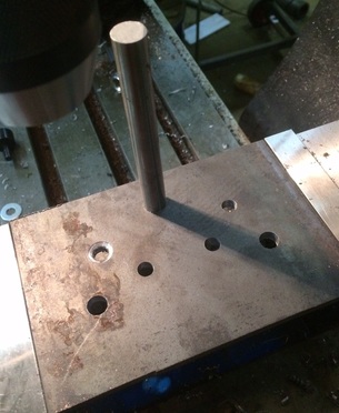
I have been thinking of buying a thermal detonator, one of the hot potato(e) type found in various places. Then I ran into a 3" stainless steel hollow sphere from Boca Bearings and figured that I could cut the sphere in half on my lathe and machine in the teeth. Once cut, I can glue the halves together for a time while I machine in the longitudinal grooves. The stainless steel should look really nice. Here is the sphere I am using, except in 76mm. These are only $14 each.
If the spheres are really spheres, I can build a temporary chuck for my lathe to hold the thing while using a diamond dremel tool on my toolholder. No clue if this will work until the spheres I ordered arrive.
If the spheres are really spheres, I can build a temporary chuck for my lathe to hold the thing while using a diamond dremel tool on my toolholder. No clue if this will work until the spheres I ordered arrive.
18 July 2015
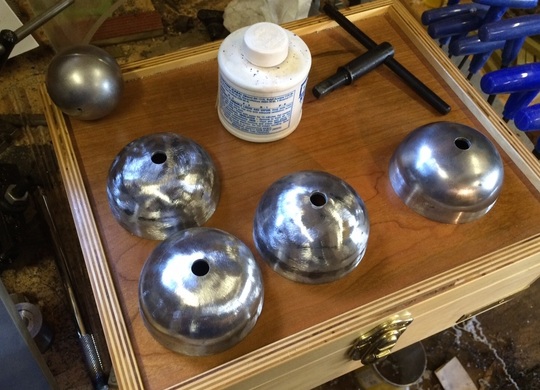
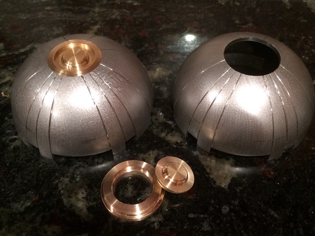
The stainless spheres didn't work out, (they are hardly spherical - although they look nice, they do not machine well) but I found some steel half-spheres from King Architectural Metals. They require a lot of work, but steel is a lot softer than stainless. I'm going to use the 3" stainless ball for a model of Sputnick. Here is some of the work I have done cleaning up the half-spheres and drilling the center holes for use in later machining.
The stainless spheres didn't work out, (they are hardly spherical - although they look nice, they do not machine well) but I found some steel half-spheres from King Architectural Metals. They require a lot of work, but steel is a lot softer than stainless. I'm going to use the 3" stainless ball for a model of Sputnick. Here is some of the work I have done cleaning up the half-spheres and drilling the center holes for use in later machining.
|
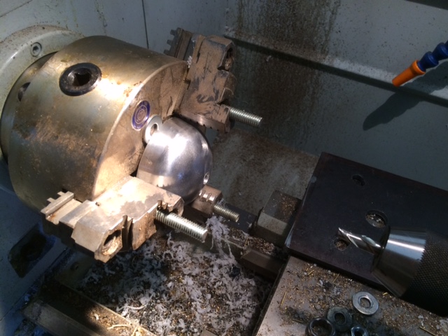
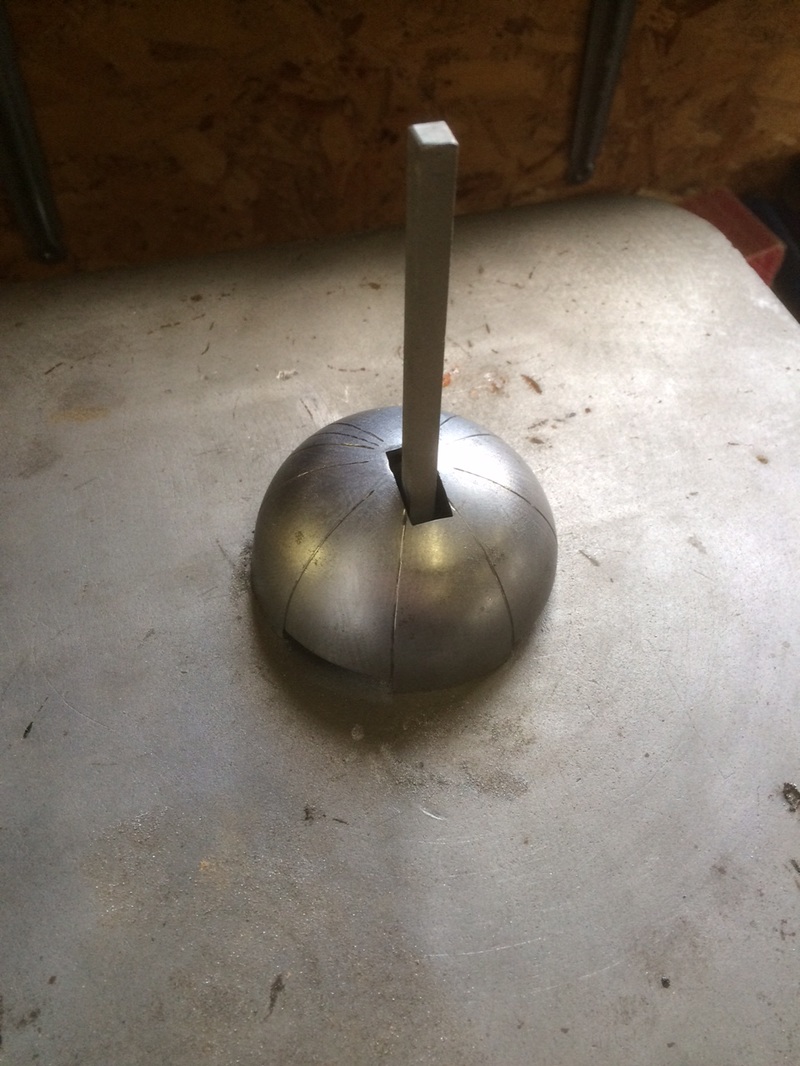
I used an old great puller plate I had made a few years back to hold the half-sphere on the chuck while milling in the center hole.
I'll have to cut the grooves in by hand. These things are just not precision enough to use the lathe. |
I found a nice 3D printed model to go by - this from Shapeways.com. It was cheap and looks good, albeit smaller than I would like. The 3D is only 2.5" and my half-spheres are 3". Of course the steel will feel far better in the hand and thermal detonators beg to be picked up. As well, the electronics package and battery (9V) will fit better in the steel thermal detonator.
If the steel half-spheres do not work out, I'll toss them out and paint up the 3D model. Ever the optimist...
If the steel half-spheres do not work out, I'll toss them out and paint up the 3D model. Ever the optimist...
|
|
9 August 2015
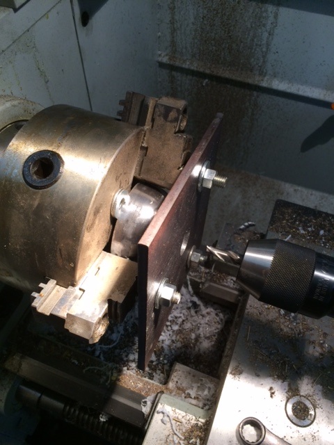
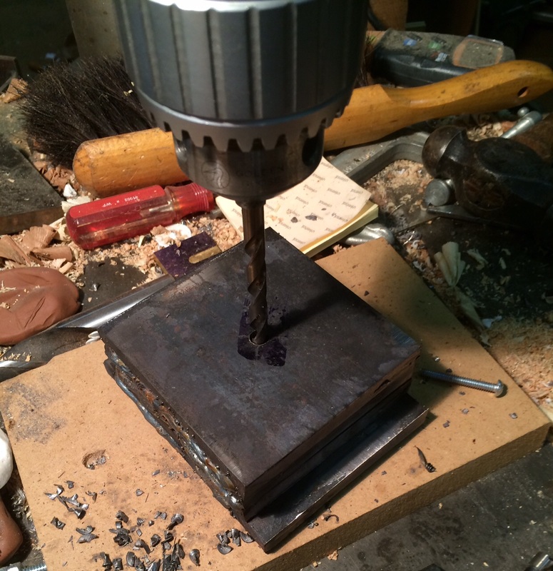
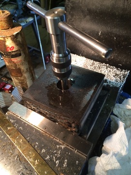
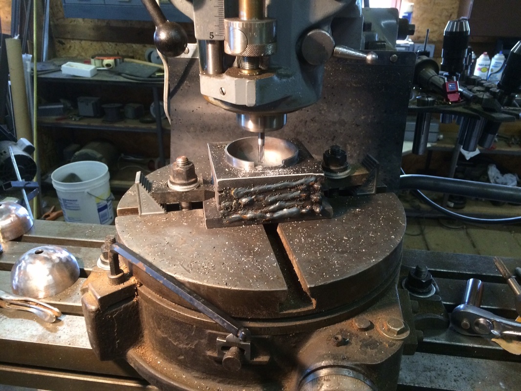
If this didn't hurt so bad, it would have been funny. In order to cut the 'teeth' in the detonator's half spheres, I need to mount them in the mill; solidly. So I welded four 1/2" steel plates to give me 2" of steel which I plan on boring out to about 2.80" with a center 3/8" threaded hole. The welding went fine, but when I drilled the 5/16" hole for the 3/8" tap, I saved time by not clamping the steel block - resulting in nearly tearing the end of my thumb off. I knew better and did it anyway, thinking that a 2" x 4" x 4" steel block being drilled with a 5/16" drill would not need clamping. I should have gotten stitches...
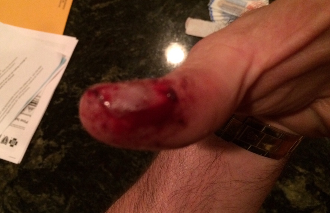
That is not my thumb nail covered in blood - that's the piece of flesh along the side of the thumb that was gouged out by the spinning metal. I have it healing now and all should be good, but it could have been much worse. This is all so pointless - I 'always' use a vise or clamp. I got lucky this time - next time I'll be smart.
If this didn't hurt so bad, it would have been funny. In order to cut the 'teeth' in the detonator's half spheres, I need to mount them in the mill; solidly. So I welded four 1/2" steel plates to give me 2" of steel which I plan on boring out to about 2.80" with a center 3/8" threaded hole. The welding went fine, but when I drilled the 5/16" hole for the 3/8" tap, I saved time by not clamping the steel block - resulting in nearly tearing the end of my thumb off. I knew better and did it anyway, thinking that a 2" x 4" x 4" steel block being drilled with a 5/16" drill would not need clamping. I should have gotten stitches...
That is not my thumb nail covered in blood - that's the piece of flesh along the side of the thumb that was gouged out by the spinning metal. I have it healing now and all should be good, but it could have been much worse. This is all so pointless - I 'always' use a vise or clamp. I got lucky this time - next time I'll be smart.
|
|
|
15 August 2015
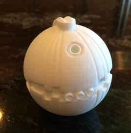
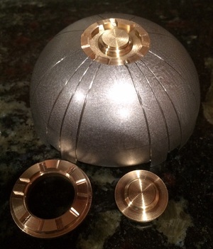
The thumb is healing nicely... about half of the gouge is knitted back together. Not anticipating a failure in the metal thermal detonator, but I have some time to do easier work, so I painted up the 3D printed model. I am ordering some blinking LEDs so it will light up when it's in its stand. |
|
|
3 September 2015
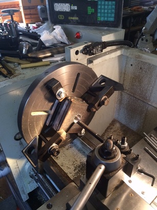
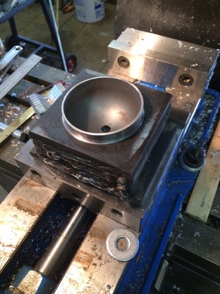
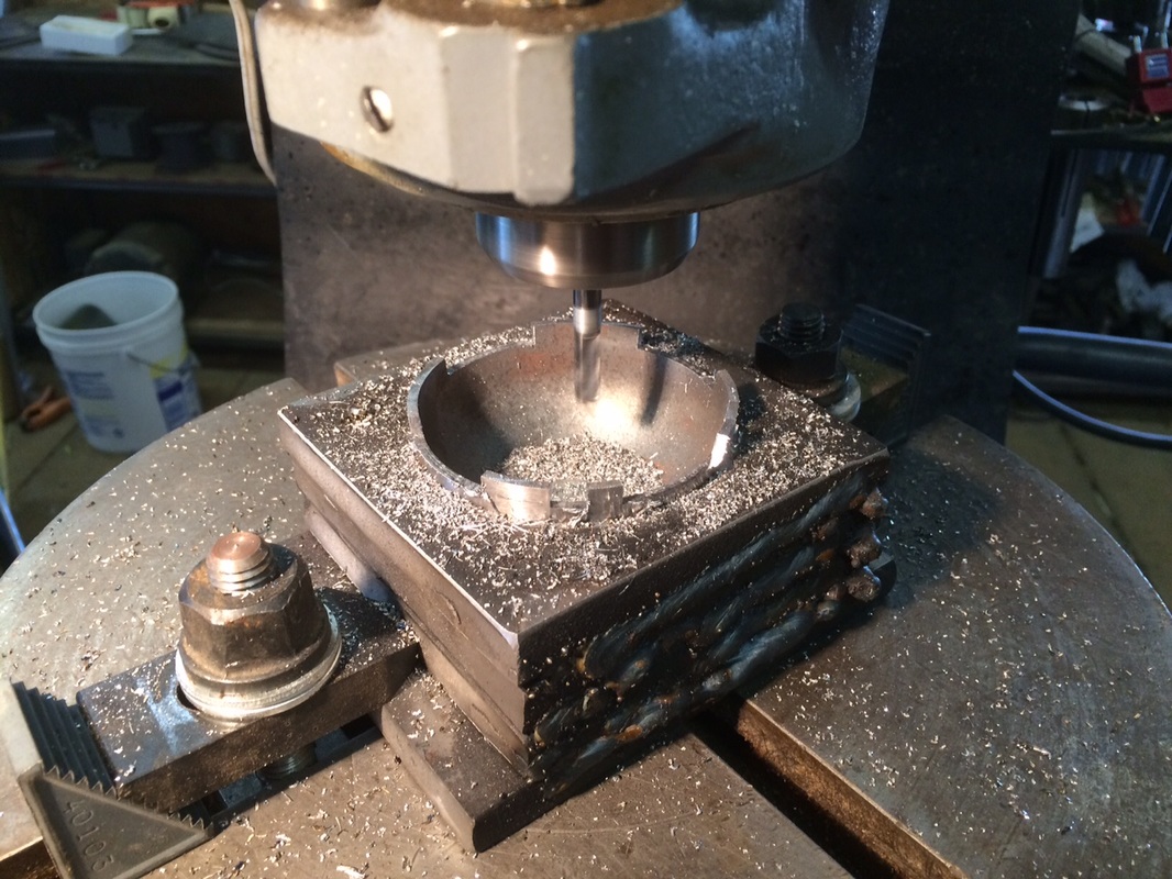
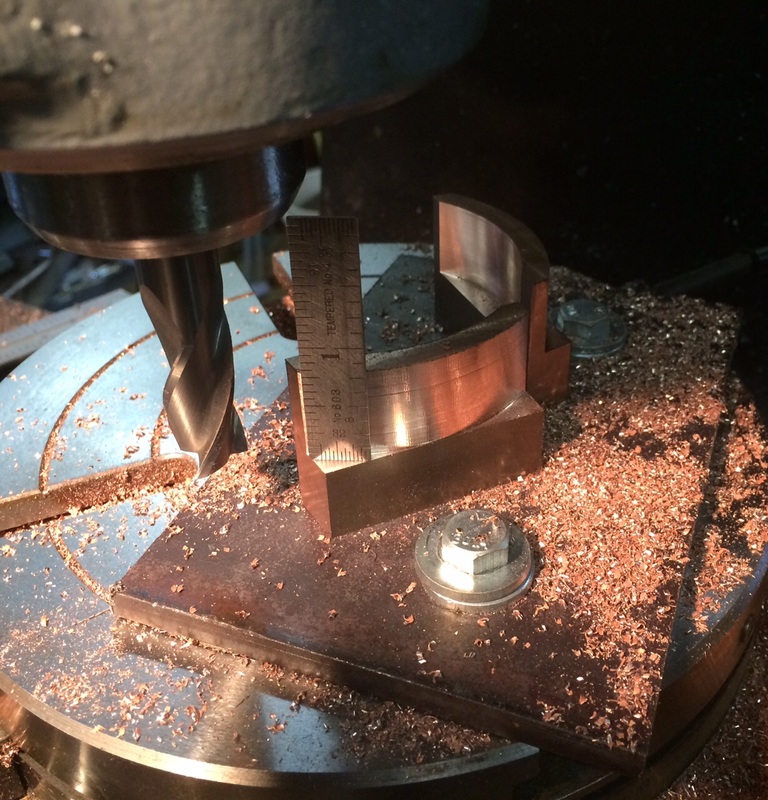
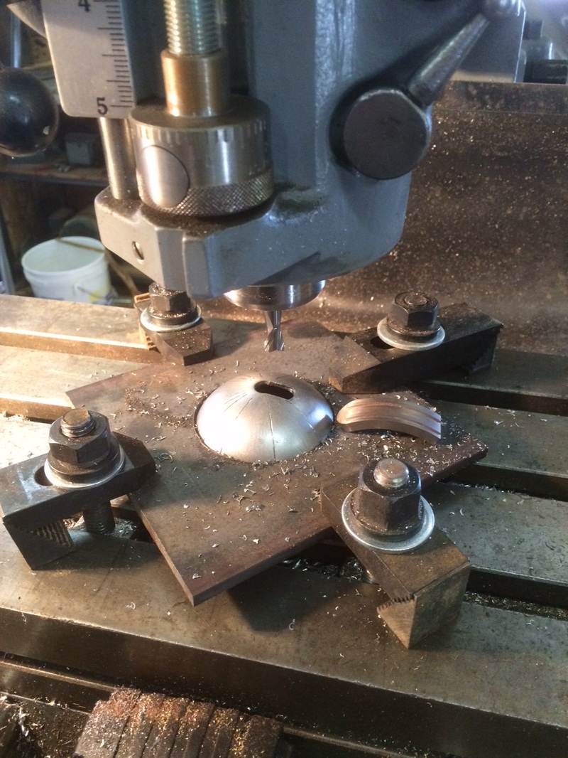
This project has taken some turns and is moving steadily (ignoring the torn thumb) but slowly. I made some progress on the cradle for machining the steel half-spheres. The cradle will be held on a rotating mill table and the half-spheres will be bolted down with a 3/8" bolt through the center. Here are a couple of pics showing the cradle. I have to say (bottom photo below) that producing a 2.950" hole in the middle of a steel block which is 2" thick, is... boring. Especially as the hole starts with a 1" drilled hole. To the right the 3/8" thread is being cut. Below right, is the steel half-sphere resting in the cradle. |
|
|
|
The 3D printed thermal detonator is complete now. The three LEDs slowly sync into various patterns. I'll build a stand with a power supply some day.
Sorry about the audio on this flash file. I'll redo this as soon as I can.
Sorry about the audio on this flash file. I'll redo this as soon as I can.
11 September 2015
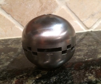
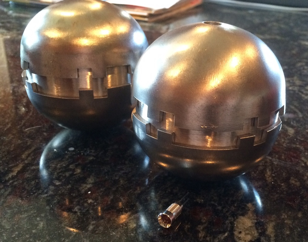
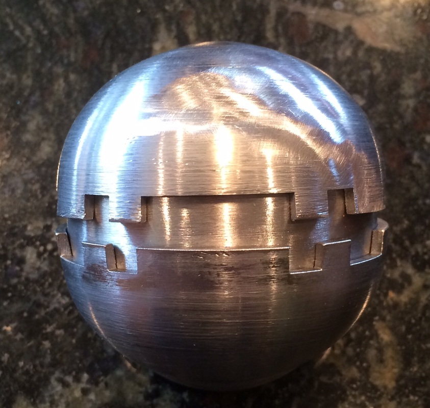
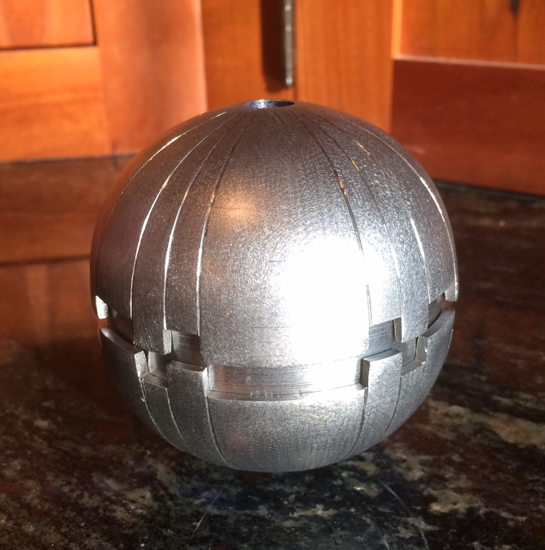
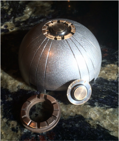
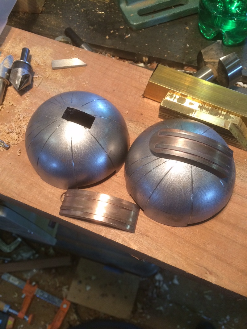
I'm not super happy with the steel half spheres - they are poorly made, but the best I can find. Machining a set which is more spherically accurate would be beyond my machine's capability - I do not own a radius cutting attachment.
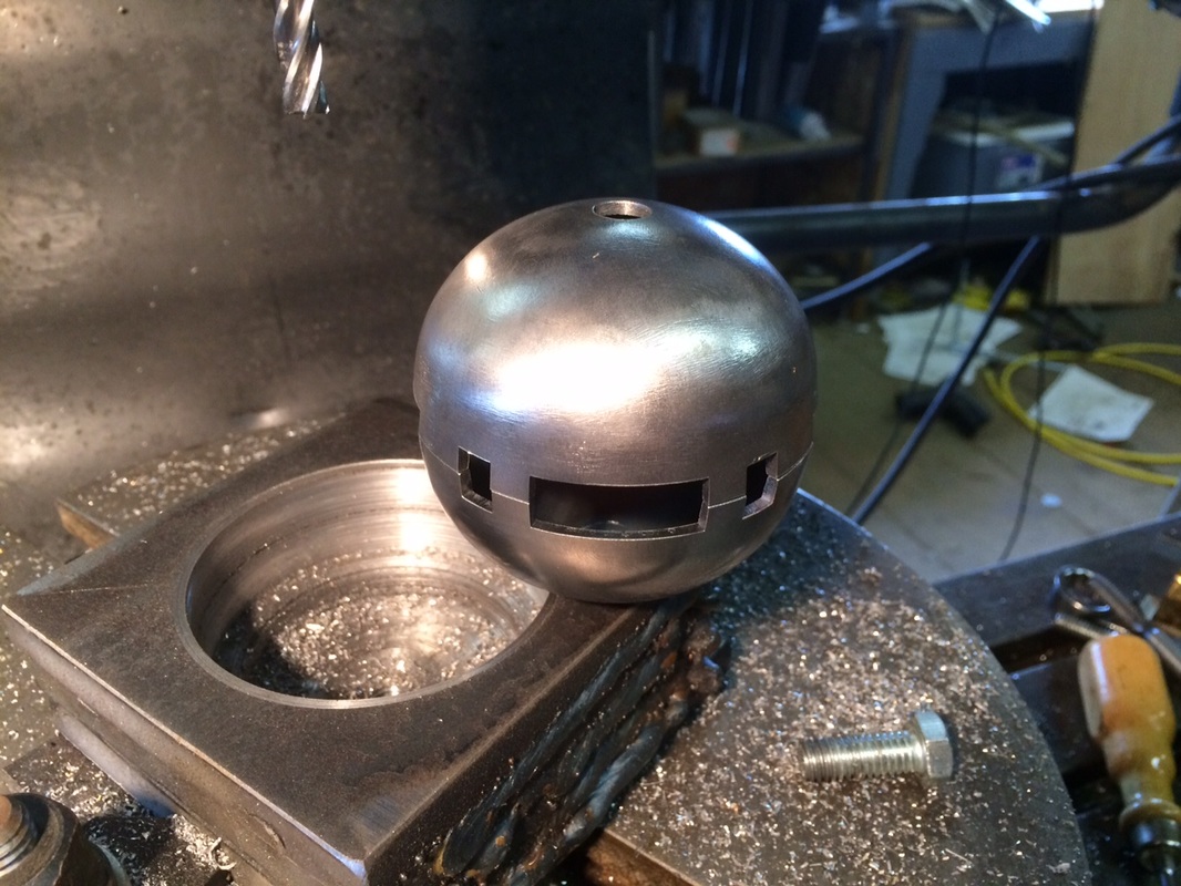
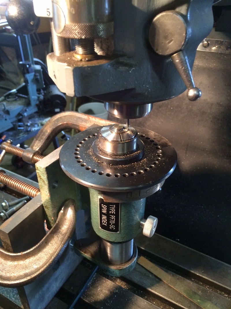
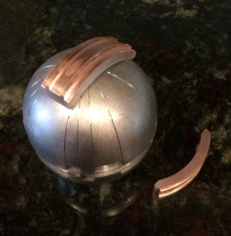
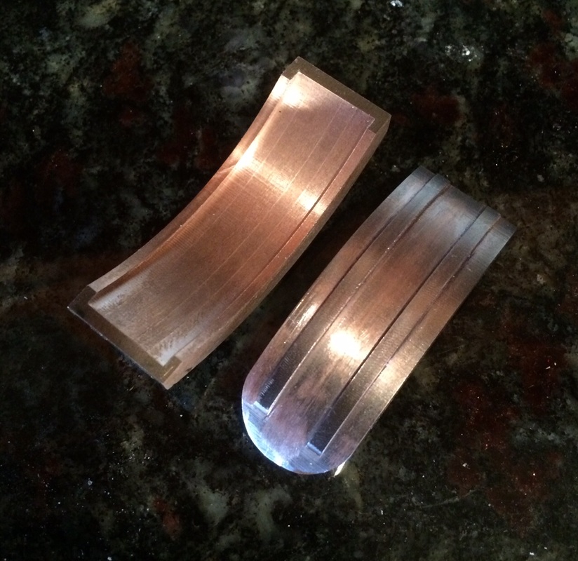
Below left, a rotary table is being used to mill the teeth into each half sphere.
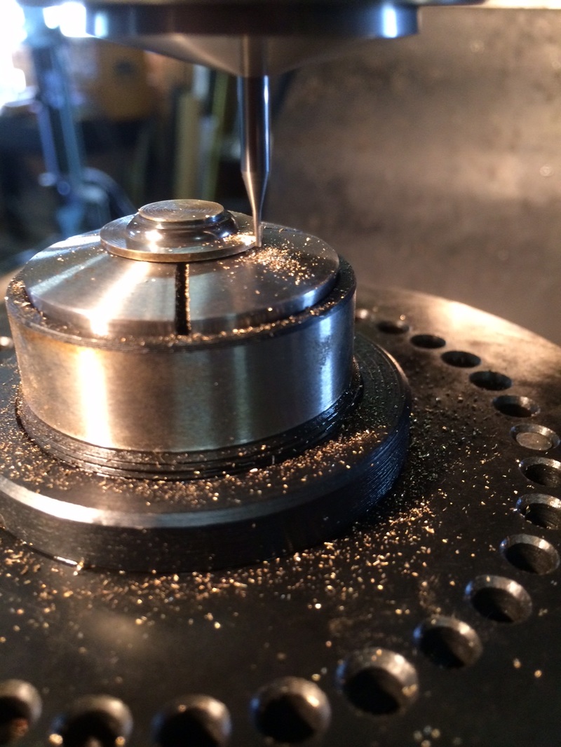
Below right is one bottom half of the thermal detonator with its teeth milled. At bottom left are two bottom halves stacked to check for accurate tooth alignment. They are exactly as I planned - a miracle if there ever was one.
Finally - bottom right are the upper and lower halves are checked for for tooth alignment.
I'm beginning to think I will pull this off...
I'm not super happy with the steel half spheres - they are poorly made, but the best I can find. Machining a set which is more spherically accurate would be beyond my machine's capability - I do not own a radius cutting attachment.
Below left, a rotary table is being used to mill the teeth into each half sphere.
Below right is one bottom half of the thermal detonator with its teeth milled. At bottom left are two bottom halves stacked to check for accurate tooth alignment. They are exactly as I planned - a miracle if there ever was one.
Finally - bottom right are the upper and lower halves are checked for for tooth alignment.
I'm beginning to think I will pull this off...
|
|
|
|
12 September 2015
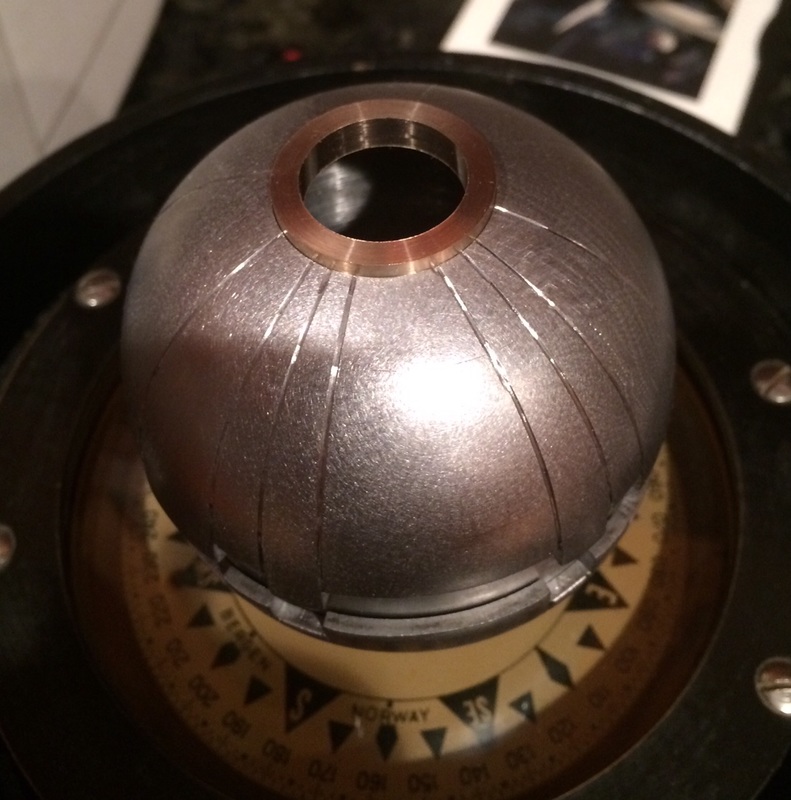
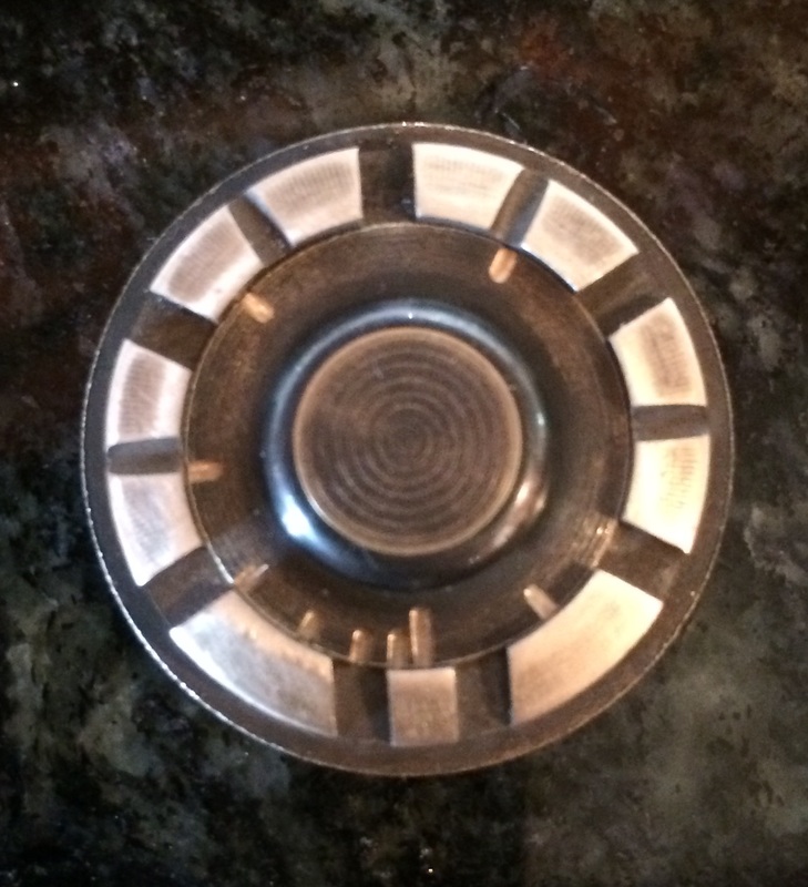
The LED ring is machined for the thermal detonators. Shown is the steel stock I used to machine it. This is all I had on hand, so it required a great deal of material removal.
The LED ring is beveled on both sides to slide into the half spheres and lock into place at the correct distance for the LED bezels.
|
|
15 september 2015
|
|
|
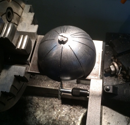
Time now to turn to machining in the longitudinal grooves on the steel half spheres. The plan is to build a jig to hold a half sphere on the lathe and use a Dremel mounted diamond wheel on the crossfeed to cut the grooves. I will likely take a shot at the jig tomorrow.
|
Here is a half sphere mounted on the new jig.
|
|
|
|
|
24 September 2015
|
25 September 2015
|
|
|
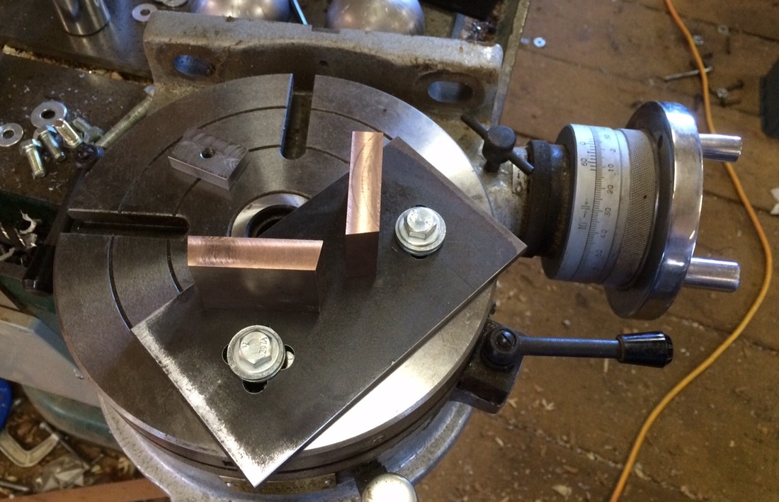
The castle cuts are done on the bronze ring. Next will be the indicator lines on the button. These will be cut on a geometric spiral at 0, 7, 17, 32, 54, 87, 137, 212, 115, and 324 degrees. My 5C collet spinner only has settings for 1 degree increments - but that is far better than its opposite.
|
Here are a couple of photos showing the cutting of the indicator lines into the button. The castle cuts were done the same way, but much deeper. The patina has already been applied, then the lines were cut in to a depth of .015" using a 1/32" cutter. I only have one of these cutters, so I was really careful not to break it, only cutting .005" at a time.
|
|
The bronze and brass pieces are treated to create a brown patina. The castle cuts were machined first, then the patina was applied. |
|
|
27 September 2015
|
29 September 2015
|
|
2 October 2015
First off, today is the first showing of "The Martian", so I am going to go see it.
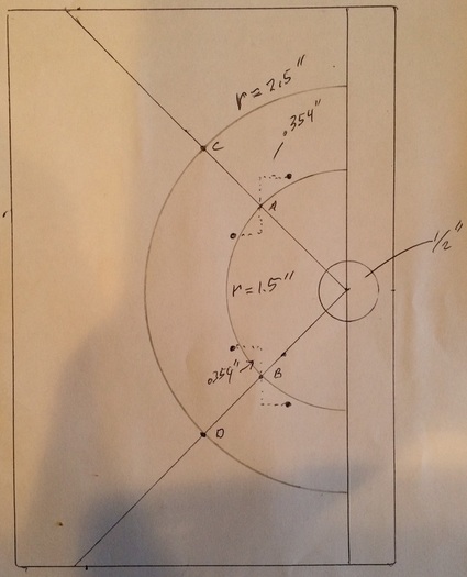
When I made the holding jig shown above, I thought I could mark out the steel plate well enough for this machining. Either I was wrong, or I made an error in machining it, because the beryllium copper pieces are not aligned. You can tell just by looking... So I made a real drawing and new calculations using the capability of my Mill's DRO, which plots a solution for hole circles. I can use that to drive the mill to the correct locations far better than a marked out plate. This should be way better... On the previous plate, I rotated my vise 45 degrees and centered as best I could on the marks. This time, I will be milling square and working off the center of the 1/2" hole at the right. The mill will calculate, using a program for eight holes, locations A-D. I can directly drill locations C and D. The holes at the left and right of points A and B are calculated using an offset from the program's locations. Simple A squared + B squared = C squared. After the plate is drilled, I will mount the rotary table, center the mill on the center of the rotary table, and mount the plate using the 1/2" hole. I can chuck up a 1/2" drill rod in the mill and lower it into the plate hole, then clamp the plate to the rotary table. All this should get me to within .001".
5 October 2015
|
|
|
6 October 2015
|
10 October 2015
|
|
|
14 October 2015
|
7 March 2016
The shop is finally warm again, so I got out and moving agin. I am milling the slots for the actuator buttons, then filing the slots into rectangles. The steel plate at the right is a die filer which oscillates the file up and down.
|
|
|
This is going to be tricky as I decided early on to drill a 3/8" hole in the half spheres to facilitate mounting them. Now I have to live with that decision which means that the slot for the mounting tab on the actuator button must be ~3/8" wide and that makes it easy for the button to rotate a bit. A 3/16 slot would have been better, but let's see how this all goes.
The Brass is for a sonic screwdriver I am playing around with. Not certain that will ever get off the ground. |
|
9 March 2016
Well this sort of stinks... The 3/8" rectangle makes it difficult to machine slop out of the beryllium copper actuator button. I should have drilled a 1/4" hole instead of 3/8" or perhaps even smaller. I'm considering welding a patch inside the top and re-machining a smaller slot. 3/16" would have been ideal.
Errata - It turns out that my beryllium copper is not so at all. It is Tungsten Copper which is much heavier.